Introduction to Three Way Ball Valve
The working principle and structural characteristics of a three way ball valve have led to its wide application in many industrial fields. The following is a detailed introduction to three way ball valves:
Ⅰ. What is a three way ball valve?
A three way ball valve is a ball valve used to control the flow of media between three pipelines. It is a fluid control valve with three fluid channels. By rotating the ball, the valve can be opened or closed, and the flow direction of the medium can be changed.
Ⅱ. What are the types of three way ball valves?
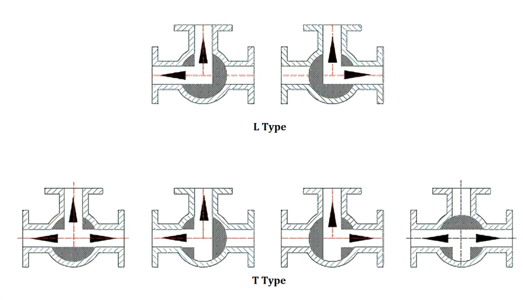
According to structures, three way ball valves can be divided into T-type, L-type and Y type.
- T-type three way ball valves can connect and disconnect the third channel among three orthogonal pipelines, playing the role of flow diversion and confluence.
- L-type three way ball valves can only connect two orthogonal pipelines and cannot keep the third pipeline connected at the same time, only playing the role of distribution.
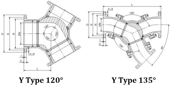
- The Y-type three way ball valve can be designed with 120° and 135° diversion ports for medium switching.
Ⅲ. How does a three way valve work?
The working principle of a three way ball valve is mainly based on its unique structure and operation mode:
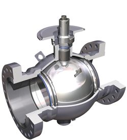
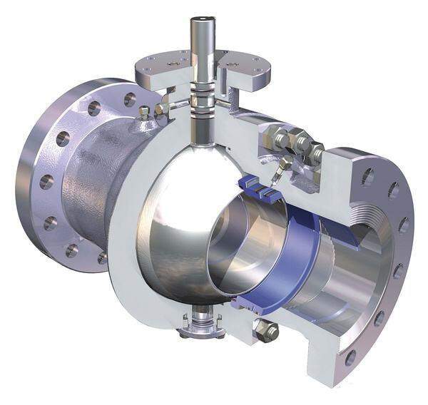
1.The structure of a 3 way ball valve.
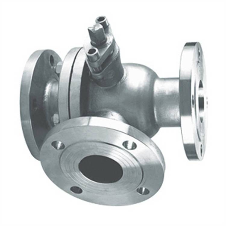
A 3 way ball valve mainly indludes three connection ends, ball core, valve stem and valve body.
- Three connection ends: each connection end features a valve seat. One side of the seat is flat, while the other has a curved surface that can tightly fit against the ball core, ensuring zero leakage.
- Ball core: the core component of a three way ball valve is a ball with three channel ports, which are respectively connected to three pipelines. The ball core determines whether the 3 way ball valve is L-type or T-type. An L-type ball core has only one groove and two holes; a T-type has three holes. The groove on the ball core is connected to the valve stem. The rotation of the valve stem drives the ball core to control the opening and closing of the valve.
- Valve stem: it is connected to the ball, and rotating the valve stem(a handwheel or an electric actuator) can drive the ball to rotate. The valve stem is designed to prevent protrusion and explosion, making disassembly and maintenance safer. There are gaskets and sealing rings at the valve stem to prevent the medium from leaking out from this part.
- Valve body: it has a simple structure and is a one-piece casting.
2.Opening and closing process.
- Opening:
When opening, rotate the handwheel counter clockwise (or start the electric actuator). The valve stem moves in the opposite direction accordingly. The angular plane at the bottom of the valve stem makes the ball disengage from the valve seat. The valve stem continues to rise and interacts with the guide pin in the spiral groove of the valve stem, causing the ball to start rotating without friction until it reaches the fully open position. - Closing:
When closing, rotate the handwheel clockwise (or turn off the electric actuator). The valve stem starts to descend, and the ball leaves the valve seat and starts to rotate. As the handwheel continues to rotate, the valve stem is affected by the guide pin in the spiral groove on it, causing the valve stem and the ball to rotate 90° at the same time. When it is almost closed, the ball has rotated 90° without contacting the valve seat. In the last few turns of the handwheel, the angular plane at the bottom of the valve stem mechanically wedges and presses the ball, making it tightly press on the valve seat to achieve a completely sealed state.
Ⅳ. Characteristics of the 3 way ball valve .
- Low fluid resistance:
the resistance coefficient is equivalent to that of a pipe section of the same length. - Simple structure:
compact design with small volume and lightweight. - Reliable sealing:
widely uses plastic sealing surfaces, ensuring excellent tightness even in vacuum systems. - Easy operation:
quick 90° rotation between fully open and fully closed positions, suitable for remote control. - Convenient maintenance:
modular design allows easy replacement of movable seals. - Erosion resistance:
in full open/closed positions, the sealing surfaces are isolated from the medium, preventing corrosion. - Wide applicability:
available in sizes from a few millimeters to several meters, suitable for high vacuum to high-pressure environments.
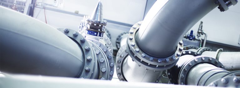
Ⅴ. Typical application fields of 3 way ball valve .
1. Petrochemical and energy.
- Switching medium flow directions in oil and gas transmission pipelines, such as crude oil distribution and LNG storage and transportation.
- Multi-channel switching in reactor feeding systems to avoid cross-contamination.
2. Pharmaceutical and food.
- Sanitary-grade three-way valves (316L material, mirror polishing) are used in CIP/SIP cleaning systems to ensure aseptic processes.
- Raw material mixing control in blending tanks, such as liquid medicine proportioning or beverage ingredient blending.
3. Heating, ventilation, and air conditioning (HVAC).
- Balancing branch flow in cold and hot water systems, such as floor heating manifolds.
- Adjusting temperature differences at the inlet and outlet of heat exchangers to optimize thermal efficiency.
4. Water treatment and environmental protection.
- Switching water flow directions in backwash filtration systems to realize automatic cleaning of filter media.
- Chemical dosing and mixing control in sewage treatment plants.
5. Special working conditions.
- High-purity gas systems (e.g., in the semiconductor industry) adopt fully coated balls to avoid contamination from metal contact.
- Cryogenically treated valves are used in low-temperature conditions (e.g., liquid nitrogen) to prevent material embrittlement.
Ⅵ. Selection Considerations for three way ball valves.
- Flow Direction Requirements: Choose L-type (for switching) or T-type (for mixing) according to the process.
- Material matching: For corrosive media, select Hastelloy or fluorine-lined valves; for high-temperature environments, metal hard seals are preferred.
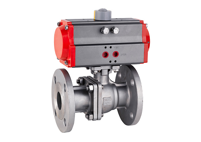
- Actuation method: Pneumatic/electric actuation is recommended for frequent adjustments, while manual valves are suitable for maintenance or low-frequency operations.
- Certification standards: Pay attention to industry certifications such as API 6D and ISO 5211 to ensure safety and compliance.
Ⅶ. Maintenance.
To ensure the normal operation and extend the service life of three way ball valves, regular maintenance is required. Specific maintenance measures include:
- Regular inspection:
Regularly check whether the components, seals, balls, and other parts of the three way ball valve are damaged or worn, and replace the damaged parts in time. - Adhere to usage specifications:
Strictly follow the usage specifications to avoid over-loading, and do not exceed the working parameter range of the three way ball valve. - Proper installation:
Select appropriate pipeline interfaces during installation to avoid over-tightening or loosening, and prevent debris or solid particles in the pipeline from entering the interior of the three way ball valve. - Regular cleaning and maintenance:
Regularly clean and maintain the three way ball valve to keep its interior clean, reduce the wear of components, and extend its service life.
In conclusion, the three way ball valve is a fluid control valve with a unique structure and excellent performance, which is widely used in multiple industrial fields. Understanding its working principle, structural characteristics, application fields, and maintenance knowledge is of great significance for the correct selection and use of three way ball valves.