
Manual Balancing Valve
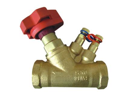
The manual balancing valve is also known as the balancing valve, static balancing valve, digital locking balancing valve, two-position regulating valve, etc. It changes the flow resistance passing through the valve by altering the clearance (opening degree) between the valve core and the valve seat, so as to regulate the flow rate.
Its action object is the resistance of the system. It eliminates the unbalanced resistance in the system, enabling the balanced distribution of the new water volume according to the proportion calculated in the design. Each branch circuit will increase or decrease proportionally at the same time.The manual balancing valve can balance and distribute the new water volume according to the proportion calculated in the design. Each branch flow will increase or decrease proportionally at the same time.
- Broad product range
With valves in sizes from DN 15 up to DN 50, mounting options with internal thread, external thread or flanges and availability of measuring tools and accessories. - Compact construction
All Way Valve balancing valves are designed to take up minimum space and be easy to install.
Technical Specifications
| Size Range | 3/4″~2″ |
| Pressure Rating | 10bar ~ 16bar |
| Face to Face Dimensions | EN 558-1, ASME B 16.10 |
| Flange End Dimension | BS 21 |
| Inspection and Test | ISO 5208 / EN 12226-2 |
Material Standard
| Part | Material | Standard |
| Body | CuZn39Pb1 / C37000 | EN12167/ASTM B135 |
| Bonnet | CuZn39Pb1 / C37000 | EN12167/ASTM B135 |
| Trim | CuZn39Pb1 / C37000 | EN12167/ASTM B135 |
| Measuring Port | CuZn39Pb1 / C37000 | EN12167/ASTM B135 |
| O-Ring | EPDM / NBR | ISO 4633 |
| Handwheel | Nylon | ISO 4633 |
Dimensions
| NPS | In | 3/4 | 1 | 1 1/4 | 1 1/2 | 2 |
| A | mm | 86.5 | 105 | 123.5 | 125 | 144 |
| H | mm | 102 | 105 | 110 | 120 | 127 |
| G | mm | G3/4 | G1 | G1 1/4 | G1 1/2 | G2 |
| SW | mm | 32.5 | 40.5 | 49.5 | 57 | 69.5 |
| KVS | m3/h | 5.77 | 8.7 | 14.2 | 19.2 | 33 |
The data is for reference only, please consult sales@wayvalve.com for details.
The manual flow balancing valve is mainly applied in the following fields:
- Heating pipeline systems in industrial and civil buildings.
- Heating systems.
- Boilers and chillers.
- Heat substations.
- District heating pipe networks.
- Cooling water circulation systems in buildings.
- Food production equipment.
Other industrial fields such as petroleum, chemical engineering, and electric power to control the flow rate of the medium and ensure the stability and safety of the production process.

What is the difference between manual and automatic balancing valves?
Manual balancing valves need to be adjusted by hand. Operators set the valve opening according to the system requirements to achieve flow balance. They are suitable for systems with stable operating conditions and are relatively simple and inexpensive. Automatic balancing valves, however, can automatically adjust the flow or pressure. They use sensors and actuators to monitor and respond to changes in the system, providing more accurate and timely balancing, especially useful in systems with variable loads.
INQUIRY
