Analysis of the Relationship Between Valve Nominal Diameter and Medium Flow Velocity
The flow rate and flow velocity of a valve mainly depend on its nominal diameter, and are also related to the resistance of the valve’s structural type to the medium. Meanwhile, they have certain inherent connections with various factors such as the valve’s pressure, temperature, and the medium’s concentration.
The flow channel area of the valve has a direct relationship with flow velocity and flow rate, and flow velocity and flow rate are two interdependent quantities. When the flow rate is constant, a higher flow velocity allows for a smaller flow channel area; conversely, a lower flow velocity requires a larger flow channel area. On the other hand, a larger flow channel area results in a lower flow velocity, while a smaller flow channel area leads to a higher flow velocity.
A higher medium flow velocity enables the use of a valve with a smaller nominal diameter, but it causes greater pressure loss and makes the valve more prone to damage. Additionally, high flow velocity can generate an electrostatic effect with flammable and explosive media, posing risks. Conversely, an excessively low flow velocity leads to low efficiency and poor economic performance. For media with high viscosity or explosive properties, a lower flow velocity should be adopted. For oil and other liquids with high viscosity, the flow velocity is selected based on the viscosity level, typically ranging from 0.1 to 2 m/s.
Under normal circumstances, the flow rate is known, and the flow velocity can be determined based on experience. The nominal diameter of the valve can be calculated using the flow velocity and flow rate.
Even if valves have the same nominal diameter, different structural types result in different fluid resistances. Under the same conditions, a larger valve resistance coefficient leads to a more significant decrease in the flow velocity and flow rate of the fluid passing through the valve; conversely, a smaller resistance coefficient results in a less significant decrease in flow velocity and flow rate.
The commonly used flow velocities for various media are shown in the table below.
| Fluid Name | Service Condition | Flow Velocity (m/s) |
|---|---|---|
| Saturated Steam | DN>200DN=200~100DN<100 | 30~4025~3515~30 |
| Superheated Steam | DN>200DN=200~100DN<100 | 40~6030~5020~40 |
| Low-pressure Steam | ρ<1.0 (absolute pressure) | 15~20 |
| Medium-pressure Steam | Ρ=1.0~4.0 (absolute pressure) | 20~40 |
| High-pressure Steam | Ρ=4.0~12.0 (absolute pressure) | 40~60 |
| Compressed Gas | VacuumΡ≤0.3 (gauge pressure)Ρ=0.3~0.6 (gauge pressure)Ρ=0.6~1.0 (gauge pressure)Ρ=1.0~2.0 (gauge pressure)Ρ=2.0~3.0 (gauge pressure)Ρ=3.0~30.0 (gauge pressure) | 5~108~1210~2010~158~123~60.5~3 |
| Oxygen | Ρ=0~0.05 (gauge pressure)Ρ=0.05~0.6 (gauge pressure)Ρ=0.6~1.0 (gauge pressure)Ρ=1.0~2.0 (gauge pressure)Ρ=2.0~3.0 (gauge pressure) | 5~107~84~64~53~4 |
| Coal Gas | – | 2.5~15 |
| Semi-water Gas | Ρ=0.1~0.15 (gauge pressure) | 10~15 |
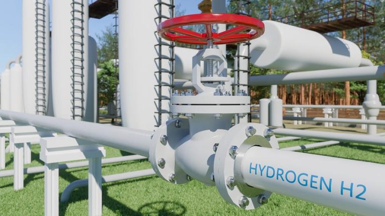
| Natural Gas | – | 30 |
| Nitrogen | Ρ=5~10 (absolute pressure) | 15~25 |
| Ammonia Gas | VacuumΡ<0.3 (gauge pressure)Ρ<0.6 (gauge pressure)Ρ≤2 (gauge pressure) | 15~258~1510~203~8 |
| Acetylene Water | – | 305~6 |
| Acetylene Gas | ρ<0.01 (gauge pressure)ρ<0.15 (gauge pressure)ρ<2.5 (gauge pressure) | 3~44~85 |
| Chlorine | GasLiquid | 10~251.6 |
| Hydrogen Chloride | GasLiquid | 201.5 |
| Liquid Ammonia | VacuumΡ≤0.6 (gauge pressure)Ρ≤2.0 (gauge pressure) | 0.05~0.30.3~0.80.8~1.5 |
| Sodium Hydroxide | Concentration 0~30%Concentration 30%~50%Concentration 50%~73% | 21.51.2 |
| Sulfuric Acid | Concentration 88%~93%Concentration 93%~100% | 1.21.2 |
| Hydrochloric Acid | – | 1.5 |
| Water and Liquids with Similar Viscosity | Ρ=0.1~0.3 (gauge pressure)Ρ≤1.0 (gauge pressure)Ρ≤8.0 (gauge pressure)Ρ≤20~30 (gauge pressure)Heating network circulating water, cooling waterPressure return waterNon-pressure return water | 0.5~20.5~32~32~3.50.3~10.5~20.5~1.2 |
| Tap Water | Main pipe, Ρ=0.3 (gauge pressure)Branch pipe, Ρ=0.3 (gauge pressure) | 1.5~3.51~1.5 |
| Boiler Feed Water | – | >3 |
| Steam Condensate | – | 0.5~1.5 |
| Condensate | Gravity flow | 0.2~0.5 |
| Superheated Water | – | 2 |
| Seawater, Slightly Alkaline Water | Ρ<0.6 (gauge pressure) | 1.5~2.5 |
Notes:
- Unit of DN value: mm;
- Unit of Ρ value: MPa.
- Gate valves have a small resistance coefficient, ranging only from 0.1 to 1.5;
- Large-diameter gate valves have a resistance coefficient of 0.2 to 0.5;
- Reduced-port gate valves have a relatively larger resistance coefficient.
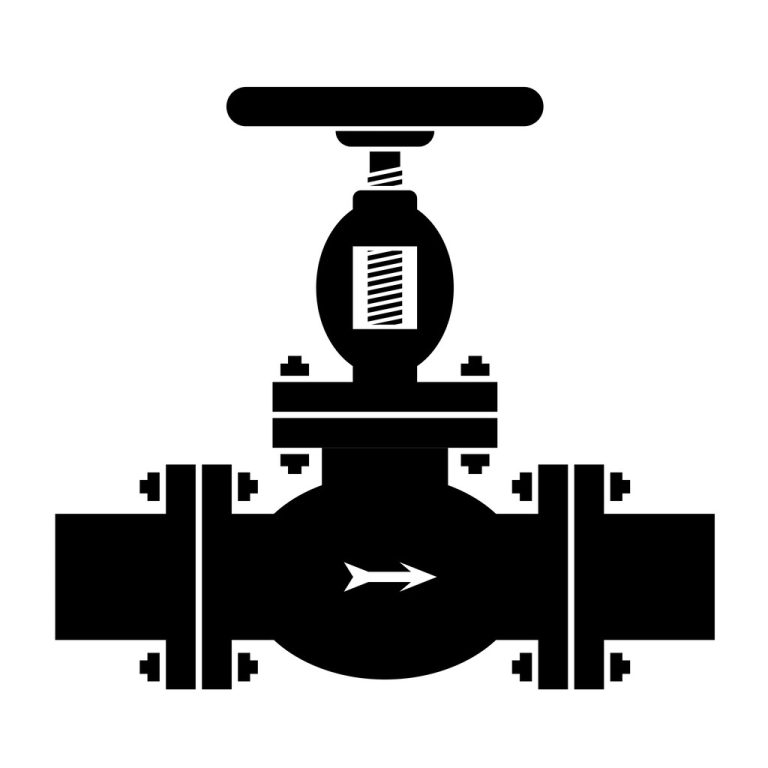
- Globe valves have a much larger resistance coefficient than gate valves, generally ranging from 4 to 7. Y-type globe valves (straight-through type) have the smallest resistance coefficient, between 1.5 and 2.
- Forged steel globe valves have the largest resistance coefficient, even up to 8.
- The resistance coefficient of check valves depends on their structure: Swing check valves usually have a resistance coefficient of approximately 0.8 to 2, among which multi-disc swing check valves have a relatively larger one;
- Lift check valves have the largest resistance coefficient, up to 12.
- Plug valves have a small resistance coefficient, usually about 0.4 to 1.2.
- Diaphragm valves generally have a resistance coefficient of around 2.3.
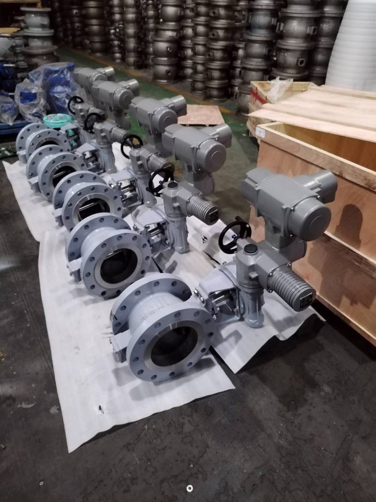
- Butterfly valves have a small resistance coefficient, generally within 0.5.
- Ball valves have the smallest resistance coefficient, usually around 0.1.
- The resistance coefficients of the aforementioned valves are values under the fully open state.
The selection of valve nominal diameter should take into account the valve’s machining accuracy, dimensional deviation, and the impact of other factors. The valve nominal diameter should have a certain margin, generally 15%. In practical work, the valve nominal diameter is determined by the nominal diameter of the process pipeline.