Factors to Consider When Converting a Manual Valve into a Pneumatic Valve
What key factors should we pay attention to when converting a manual valve into a pneumatic valve?
I. Valve Compatibility
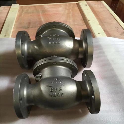
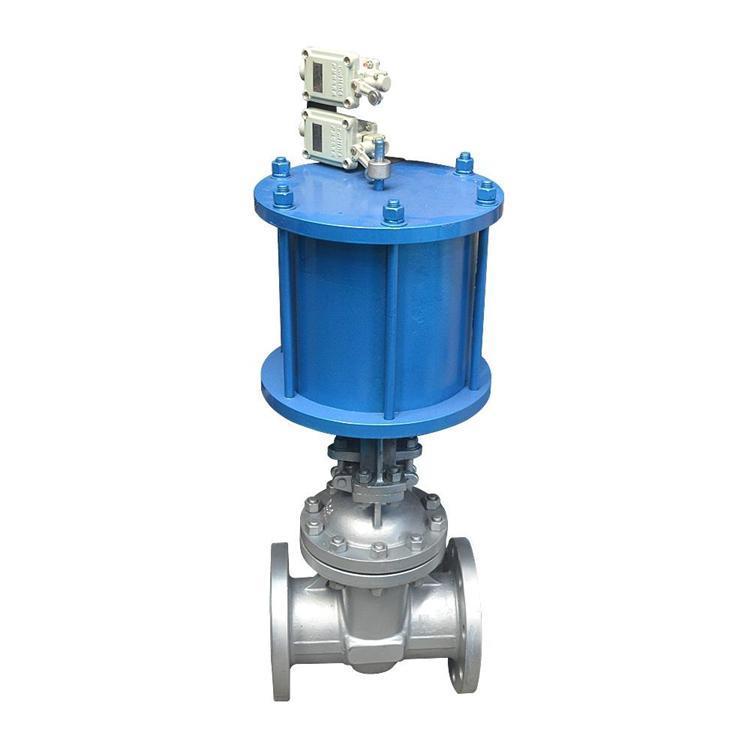
Valve Type Matching: When selecting a pneumatic actuator, the primary task is to ensure that it matches the type of the existing manual valve. Different types of manual valves, such as gate valves, globe valves, butterfly valves, and ball valves, etc., have different structures and operation methods, so the required pneumatic actuators will also vary.
For example, gate valves need to overcome a relatively large frictional force when opening and closing, so a pneumatic actuator that can provide sufficient torque should be selected; while butterfly valves require less torque, but they have higher requirements for the angular control accuracy of the actuator.
Valve Size and Pressure Rating: Parameters such as the torque output and thrust of the pneumatic actuator must comply with the size and working pressure rating of the valve. Generally speaking, the larger the valve diameter and the higher the working pressure, the greater the required operating force. Therefore, when selecting a pneumatic actuator, it is necessary to calculate the required torque or thrust according to the nominal diameter and working pressure of the valve to ensure proper selection.
Connection Method Compatibility: It is also necessary to carefully check whether the connection method of the manual valve (such as flange connection, threaded connection, etc.) is consistent with the installation method of the pneumatic actuator. If the two are not compatible, it may be necessary to modify the valve or the actuator, or use suitable connecting parts. For example, the specification of the connection flange of some manual ball valves may not match the flange specification of common pneumatic actuators. In this case, special flange connecting parts need to be customized to ensure correct installation.
II. Requirements for the Air Source System
Air Source Pressure and Flow: The key to the stable operation of a pneumatic valve lies in the appropriate supply of air source pressure and flow. The air source pressure usually needs to be set according to the working requirements of the pneumatic actuator, and it is generally in the range of 0.4 to 0.8 MPa, but the specific requirements may vary depending on the actuator. At the same time, it is necessary to ensure that the air source flow can meet the needs of the actuator during rapid response to avoid slow valve movement due to insufficient flow. In a system where multiple valves act simultaneously, the total air source flow needs to be calculated to ensure the normal operation of each valve.
Air Source Quality: The air source must be kept clean and dry to prevent the ingress of impurities, moisture, and oil. Impurities may block the air path of the pneumatic actuator and affect the valve operation; moisture may freeze in a low-temperature environment, causing air path blockage or component damage; and oil may contaminate the internal seals and components of the valve, shortening its service life. Therefore, devices such as filters, dryers, and oil mist separators are usually installed in the air source system to ensure the quality of the air source.
III. Control System and Installation Debugging
Control Signal Matching: Select an appropriate control method and signal type for the pneumatic valve to ensure compatibility with the existing control system. The control methods may include on-off control (such as a two-position three-way solenoid valve) and analog control (such as an electro-pneumatic converter to adjust the valve opening). It is necessary to select according to the actual needs and ensure that the control system can provide the required signals, such as a 24V DC or 4-20mA current signal. At the same time, attention should be paid to the signal transmission distance and anti-interference ability to prevent signal distortion or loss.
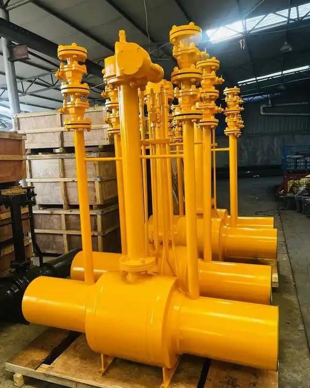
Installation Position and Space: When installing the pneumatic actuator, its position and the surrounding space should be considered to facilitate operation, maintenance, and repair. The actuator should be kept away from high-temperature, humid, or corrosive environments. In addition, ensure that the actuator has sufficient space during operation to avoid collisions with surrounding equipment or pipelines. For example, a large pneumatic butterfly valve actuator needs to reserve enough space for disassembly and repair.
Debugging and Calibration: After the installation is completed, the pneumatic valve must be debugged and calibrated. This includes checking whether the valve opens and closes smoothly, whether the stroke is accurate, and whether the sealing performance is good. During the debugging process, the valve operation can be optimized by adjusting the limit device of the actuator and the air source pressure. At the same time, the control system needs to be calibrated to ensure that the control signal is consistent with the valve operation. For example, a pneumatic control valve with analog control needs to calibrate the opening-signal curve to ensure control accuracy.